Poultry High Tech from 1887
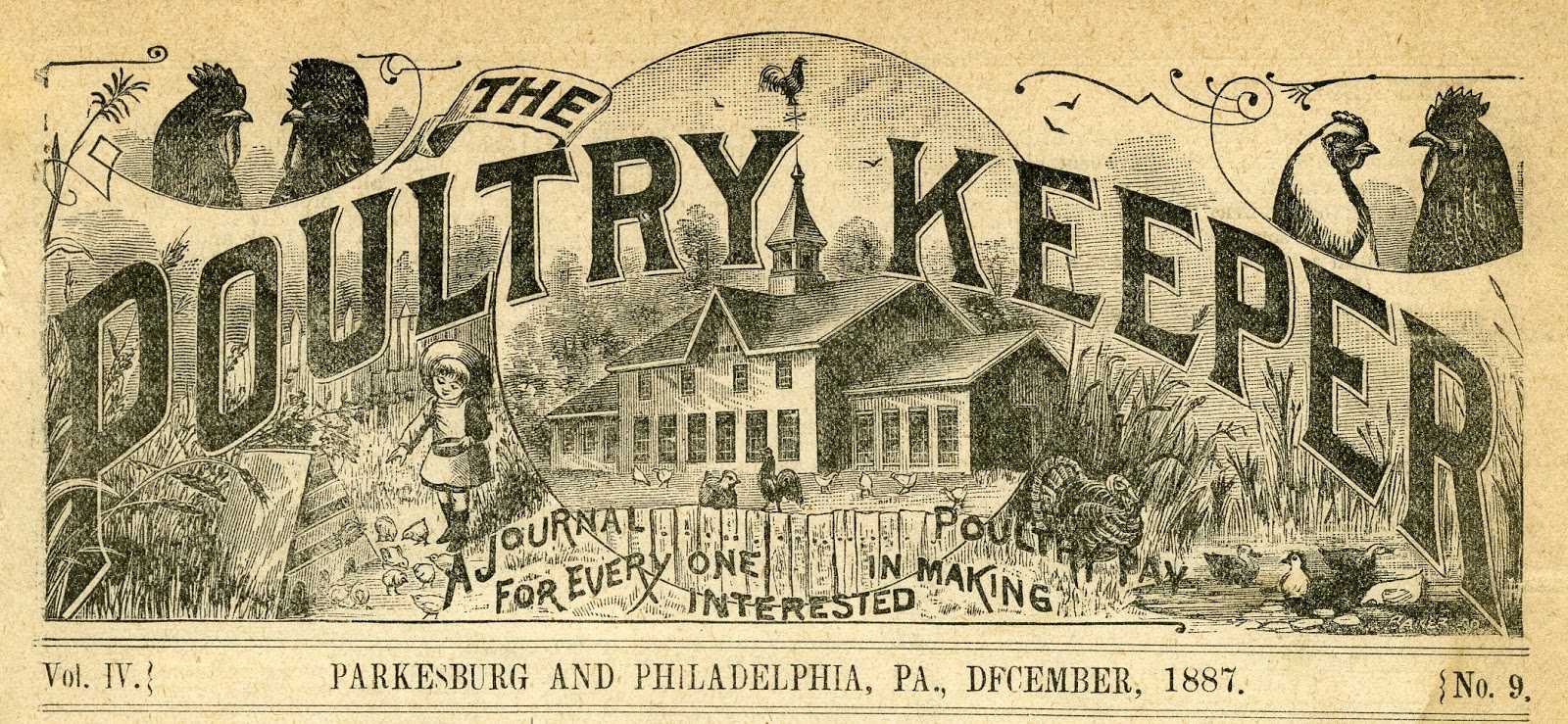
I recently came across a copy of an old magazine for poultry enthusiasts called The Poultry Keeper that was dated December, 1887. This journal for poultry
enthusiasts was published in Parkesburg & Philadephia, Pennsylvania and
was created for people who were “interested in making poultry pay," or so says the banner.
Then as now, there was a good deal of interest in
do-it-yourself projects. Perhaps, back then chicken owners really didn’t have
much of a choice; you made it yourself or you did without.
Let’s remember that in 1887 most men who
fought in the civil war were still alive, over 40% of American’s lived on farms
(versus 2% today), and the first Sears Roebuck catalog wouldn’t be published until the following year. If you
didn’t build it yourself, you didn’t
have it.
Two small articles in the Poultry Keeper describing DIY
projects caught my eye. I thought it would be fun to share these with you. They
represent “high” tech poultry equipment design for the time.
Incubator Project
An incubator is a device that keeps fertilized eggs warm so
that chicks can be hatched. Nowadays, a number of companies make very good
electric units for home enthusiasts. These incubators include both a heating element and a thermostat. Plug them in, and they’re ready to go.
But in 1887, it wasn’t that easy…..
People had to build their own incubators and so The Poultry
Keeper provided design ideas and simple instructions. One design used hot air
to warm the incubator and a second design used hot water. That notwithstanding,
both function in pretty much the same way.
An oil lamp is used as a heat source and functions like a
boiler. It heats either air or water, that is then allowed to circulate into a
chamber within the incubator to provide heat. If you’ve ever lived in a house
that was heated by a steam radiator, you’ll understand exactly how these
systems work.
The design shown below is the hot air system. A tin cone
connected to a pipe is placed over the globe of an oil lamp. Heat generated by
the oil lamp is transmitted to the air within the lamp and is allowed to circulate
into the top of the incubator by way of the pipe.
The second design is similar, but here a water chamber is constructed
to fit over the globe. The lamp heats water in the chamber and this then
circulates into a water tank within the incubator. The
water is then recirculated -- Cooler water in the incubator is driven into the
lover part of the lamp’s water chamber where it is re-heated and driven back
into the incubator.
A Primitive Thermostat
In the same issue, a reader, Mr. G. A. Hayne of Dagerville,
Iowa sent a drawing of a “regulator” that could be placed within the incubator
to help control the temperature.
However, unlike today’s thermostats, this
device did not automatically adjust the temperature. Rather, it sounded an
alarm that would let the chicken owner know that the brooder was either too hot
or too cold. The owner would then need to manually adjust the wick within the
lamp to either increase or decrease the heat.
Here’s how it worked…….
In figure #1 (cross-sectional view of the regulator) a bell [B] is connected to what appears to be a battery [L]. When a connection is made between the two
polls of the battery, current runs through the circuit and causes a bell to
ring. There is a switch [R] that sits between the two poles of the battery that is
temperature sensitive. This switch is the heart of the “regulator.”
It is constructed of a thin sheet of metal riveted to a thin
sheet of rubber. The rubber expands or contracts depending on the temperature
in the environment. Therefore, it will either bend upward or downward. The
extent of the bending depends on the temperature in the ambient environment. If
it bends in either direction sufficiently (In other words the temperature is too
hot or too cold) the metal end of the regulator will come in contact with one
of two metal screws [I and J]. When this contact occurs, the circuit is closed and allows
electricity to flow from the battery to the bell, sounding an alarm that calls
the owner over to make an adjustment to the oil lamp.
To make the system work, you only need to set the right distance
between the two screws and the metal/rubber switch. This is done by setting the lower and upper
temperatures using a thermometer.
When the temperature is at the lower limit,
you turn one of the screws till it just touches the metal sheet (causes a connection).
Then turn up the heat and wait till the temperature reaches the upper limit of
what you want and then turn the second screw till it just touches the metal
sheet (causes another connection). The regulator is now set to ring whenever
the temperature changes beyond the upper and lower temperature limits.
Would this contraption work? I think so! Modern thermostats
operate along pretty much the same principle but instead of a metal sheet, the
connection is made using a bubble of liquid mercury (like that used in an oral
thermometer). When the temperature increases, the mercury expands and creates
an electrical connection that turns on your heating unit.
How accurate would it be? It really depends on the materials
you use. However, in 1887 it would have been as high tech as it gets. Nest
Thermostat move over!


Comments
Post a Comment